
A New Technology for Optimized UV-A-Light Energy Transfer to the Cornea in Corneal Crosslinking for Keratoconus
Abstract
Purpose
The conventional irradiation technique in corneal crosslinking for keratoconus is characterized by a free irradiation path and parallel light rays directed to the corneal surface. This can cause treatment failures resulting from the steep and irregular corneal curvature as well as from eye and head movement. Here we present a a new and improved irradiation technology for corneal crosslinking (CXL) in keratoconus to avoid such treatment failures.
Materials and Methods
The presented technology is characterized by a closed irradiation channel which is lined inside with a diffusely reflecting layer and which is mounted to the eye via a suction ring. The effective intensity transferred to a curved photodetector representing the curved cornea of some 7 mm radius was measured for both, the conventional and the new technology. The results were compared with related calculations.
Results
The UV-A irradiation transferred to a curved cornea of some 7 mm central radius varies across the irradiated area by a factor of 2 for the conventional technology. At a distance of already 2 mm from the vertex the transferred UV-A intensity falls below 2/3 of the central intensity which might affect the effectivity of the treatment. The new technology can keep the intensity transferred to the cornea at a constant level across the entire irradiated area.
Conclusion
The new irradiation technology can considerably improve the energy transfer to the cornea since the effective intensity at the cornea becomes independent from the corneal shape, the eye movement and the head movement, respectively. This may probably reduce the failure rate of corneal crosslinking in the future.
Article Information
- Received
- Accepted
- Published
Academic Editor: Asaad Ghanem, Mansoura ophthalmic center, mansoura university, mansouraam.
Checked for plagiarism: Yes
Review by: Single-blind
Copyright © 2024 Albert Daxer, et al.
 This is an open-access article distributed under the terms of the Creative Commons Attribution License, which permits unrestricted use, distribution, and reproduction in any medium, provided the original author and source are credited.
Corresponding author: Albert Daxer, CISIS Keratoconus, Center, Wiesel burg, Austria, Department of Ophthalmology, Medical University Innsbruck, Austria —
Competing Interests
The authors have no conflict of interest to declare.
Funding
No specific funding statement was provided by the authors.
Data Availability
No data-availability statement was provided by the authors.
Citation:
Introduction
The invention of corneal crosslinking (CXL) was a milestone in the treatment of ectatic eye diseases which prevented a number of eyes from progression to legal blindness and cornea transplantation.1 Since the first publication of CXL treatment results in keratoconic eyes, the irradiation technique characterized by a free irradiation path and parallel UV-A light rays remained virtually unchanged.2 The failure rate of CXL (percentage of eyes suffering from further progression despite CXL) in ectatic eyes was reported to range from 7.5% to some 25% in average and high preoperative maximum keratometry readings (K-value) were identified as a significant risk factor for further progression and re-treatment.3-5 Treatment failures are therefore most likely the result of the steep and irregular shape of keratoconic corneas as well as from eye and head movements during irradiation. Here we present a new technology to avoid such potential treatment failures.
Materials and Methods
The effective intensity measured by a curved photodetector of some 7 mm radius representing a cornea were measured from both, the conventional crosslinking technology and the new technology (Figure 1, Figure 2). The conventional technology is based on a free irradiation channel with parallel light rays where the eye can move relative to the irradiation beam (Figure 3 left). The new technology uses an irradiation channel which is lined inside with a diffusely reflecting layer and mounted at the eye by means of a suction ring during treatment (Figure 3 right) 6. The diffusely reflecting layer by which the irradiation channel is lined at the inner wall reflects every light ray which strikes that layer diffusely in every direction back into the channel. Since there exists no curved electronic detector system for UV-A irradiation we used a photographic paper strip of suitable sensitivity to as a representation of a curved cornea (Figure 1 b, Figure 2 b). The strip was bended in a way that the curvature had a 7 mm radius (Figure 1 a, Figure 1 b). Figure 1a shows how the curved photographic paper strip was exposed to a typical conventional CXL UV-A irradiation device (CSO Vega CBM X Linker, CSO, Italy) of 3 mW/cm2. Figure 2a shows how the curved photographic paper strip was exposed to the new device (Keralux, Dioptex GmbH, Austria), which consists of a tubular pathway for the UV-A light. The tube is lined with a diffusely reflecting layer at its inner surface. The device has an intensity of 9 mW/cm2 at the distal opening of the tube and the same wavelength of 370 nm as the conventional device. The blackening of the photographic paper strip represents the relative distribution of the effective intensity at the curved surface (cornea) as a measure of the distribution of the transferred UV-A energy to the corneal surface. The irradiation time was a small fraction of a second in both cases. Figure 1 a and Figure 2 a are just demonstrations how the exposure of the detector strip was applied to the irradiation. The real exposure took of course not place at daylight but in a dark room. The maximum of the transferred energy (blackening) was related to the specified intensity output of the device at treatment distance. Keralux is a single use device controlled by built-in micro- electronics. It is powered by a battery inside the device which makes it independent from external power supply. It was approved as a medical device according to MDD in the European Union in 2018. The clinical application is shown in Figure 4 and Figure 5 where the device is mounted to the eye via a suction ring. The suction ring is designed in a way that the intra-ocular pressure does not rise to an extend where the central artery is occluded. The patient, therefore, does not suffer from temporary vision loss which can easily be verified during the procedure by presenting an object such as the fingers of the hand of the surgeon to the patients treated eye.
Figure 1. Shows the experimental setup and the results for the conventional irradiation technology. a) How the curved strip of a photographic paper which represents the cornea was exposed to the UV-A light beam. b) Blackening of the photographic paper due to exposure to the UV-A light beam. c) Related intensity distribution at a cornea surface across the irradiated area derived from the blackening. 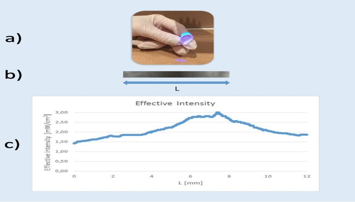
Download figure
Figure 2. Shows the experimental setup and the results for the new irradiation technology. a) How the curved strip of a photographic paper which represents the cornea was exposed to the UV-A light beam. b) Blackening of the photographic paper due to exposure to the UV-A light beam. c) Related intensity distribution at a cornea surface across the irradiated area derived from the blackening.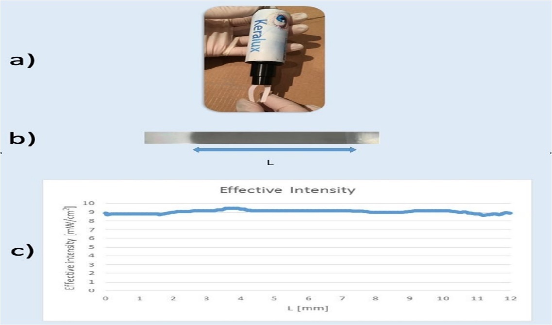
Download figure
Figure 3. Shows the irradiation characteristics of both, the conventional technology (left) and the new technology (right).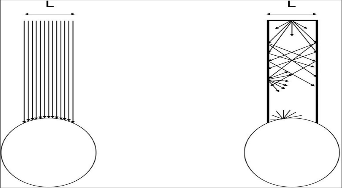
Download figure
Figure 4. Shows the clinical application of the new device demonstrating the possibility of treating both eyes of a patient at the same time.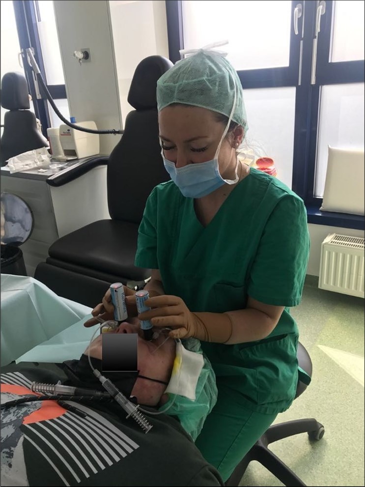
Download figure
Figure 5. shows the clinical application of the new device demonstating the possibility of treating multiple patients at the same time. 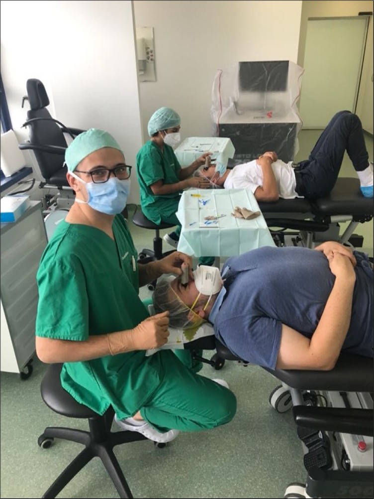
Download figure
Results
Figure 1b shows the blackening of the photographic paper strip after the exposure to the conventional device and Figure 1c shows the related effective intensity at the curved surface according to the blackening (the amount of blackening). The transferred intensity to the cornea at the vertex corresponds to the intended treatment intensity of 3 mW/cm2. This value drops rapidly when measuring away from that point. The intensity varies by a factor of 2 over the entire irradiated area. The intensity only 2 mm from the vertex drops already to 2/3 of the intended intensity namely to 2 mW/cm2.
Figure 2 b shows the blackening of the photographic paper after exposure to the KERALUX device. There is a homogeneous blackening and a homogeneous intensity transfer to the corneal surface across the entire surface (Figure 2 c).
Discussion
If parallel light rays strike a curved target such as the cornea, the intensity at the surface depends on the angle under which the rays strike that surface. In case of the cornea this is shown in Figure 6. The highest (intended) intensity of 3 mW/cm2 is I0, which is present at the top (vertex) of the cornea where the light rays strike the cornea at a right angle. The intensity I at a certain distance away from the vertex where the light rays strike the corneal surface under an angle α the intensity I yields I = I0.sin(α).
Figure 6. shows the relation between the irradiation intensity of an incident beam and the angle between the irradiated surface and the incident beam demonstrated on a curved surface like the cornea: I(α) = I0.sin(α). 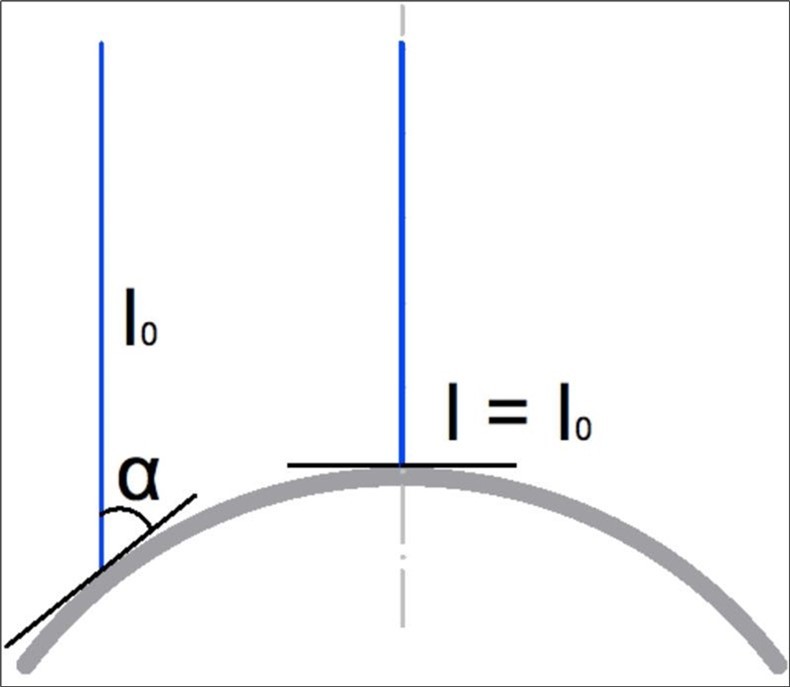
Download figure
The result is a very inhomogeneous effective intensity at the corneal surface (Figure 1 c). In the case of Keralux, the calculation shows a very homogeneous effective intensity distribution over the entire curved surface (Figure 2 c), because the multiple diffuse reflections at the inner wall of the irradiation channel along the irradiation path result in a homogeneous irradiation because the light rays strike the corneal surface at every point across the irradiated area from virtually all directions.
Already the relatively homogeneously curved target resulted in an extremely inhomogeneous intensity distribution across the entire irradiated area. Since a cornea suffering from keratoconus is steeper and more irregular the deviation from a good intensity profile at the corneal surface should be much more pronounced in the treatment of keratoconic eyes. This is in particular the case for very steep corneas which is in agreement with the clinical findings.3-5 The steeper the cornea the worse the energy transfer (effective intensity) and the higher the failure rate of the treatment under the conventional technology. Further sources of errors which probably affects the effectivity of the treatment under a free irradiation path with parallel light rays may be eye and head movements and the variation of the distance between the light source and the corneal surface during the treatment.
Since the new technology avoids all these sources of error one may expect better results
with less treatment failures by the new technology. Further studies on a larger number of cases over a longer period of time are required to answer that question.
In addition to possible medical advantages the new technology can also improve patient management of an ophthlamic practice since it allows the treatment of both eyes of a patient (Figure 4) as well as the treatment of multiple patients (Figure 5) at the same time.
References
- 1.Spoerl E, Huhle M, Seiler T. (1998) Induction of cross-links in corneal tissue. Exp Eye Res. 66, 97-103.
- 2.Wollensak G, Seiler T Spoerl. (2003) Riboflavin/ultraviolet-a-induced collagen crosslinking of keratoconus. , Am J Ophthalmol 135-620.
- 3.Lenk J, Herber R, Oswald C, Spoerl E, Pillunar L E et al. (2021) Risk Factors for Progression of Keratoconus and Failure Rate After Corneal Cross-linking. J Refract Surg. 37, 816-823.
- 4.Koller T, Mrochen M, Seiler T. (2009) Complications and failure rates after corneal crosslinking. J Cataract Refract Surg. 35, 1358.